
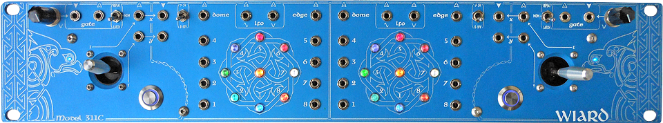
Model 311C Dual JAG Controller
JAG Controller | Sequantizer | Envelator | Classic VCO | Waveform City | Omni Filter | Borg Filters | Mixolator | Woggle Bug | 19" Rack Mounting Frame | Accessories
Introduction
The 311C Dual JAG Controller is based on the rare and long out of production 311B "New Controller", however it is not just a re-issue. The 311C is packed with new features and improvements, providing the equivalent functionality of eight distinct modules in one streamlined unit (JAG (x2), Joystick (x2), Multimode Gate (x2), Quadrature LFO (x2)).
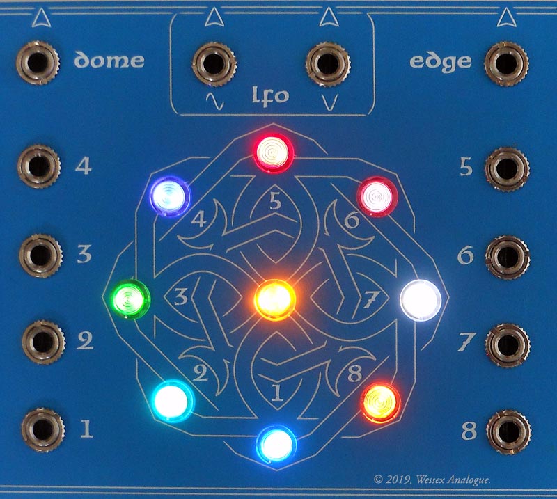
Dominating the 2U panel are two JAGs (Grant Richter's Joystick Axis Generator), illuminated with large LEDs in nine colours. These devices take two incoming X/Y voltage components and map them into various combinations, providing 10 different outputs. The outputs are represented by LED indicators. "Dome" represents proximity to the centre. "Edge" represents proximity to any edge. The JAGs can be controlled with the included joysticks (which are pre-patched to the JAG inputs), producing a movement on the JAG which follows the position of the joystick, and this is probably the easiest way to visualise and understand how the JAGs work with CVs. Using the JAGs to process audio rate signals can produce some very interesting effects!
The two joysticks can be used in either bipolar (±5V) or unipolar(0-10V) modes (polarity of joystick outputs will change to follow the JAG input polarity switch). Joystick voltage outputs are provided on the panel, and can be used either in combination with or separate from the JAGs.
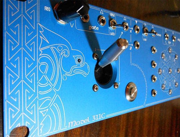
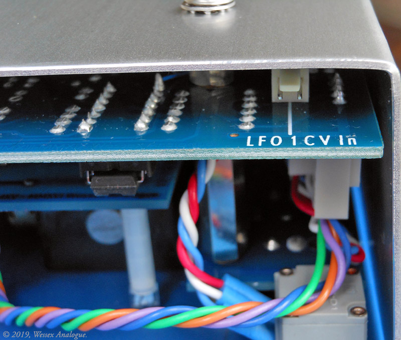
In the top corners, there are frequency controls for the two on-board LFOs. These output a sine and cosine waveform, with an extremely wide frequency range and provision for voltage control via a header on the underside of the main board. (Pre-assembled wiring to panel mounting jacks may be ordered as an option.) Sine and cosine can be patched to the inputs of a JAG for circular modulation at LFO rate (swap the inputs to reverse direction). Patching two different frequency LFOs to the inputs of a JAG will produce Lissajous shaped modulation! The LFO Cosine is pre-patched to the Gate input on each side, but this can be overridden by patching into the Gate input jack.

The multi-mode gate circuits will convert any input voltage to a 10V gate signal. Depending on the position of the mode switch, the gate will behave differently. In the centre switch position, the gate button is momentary, and will turn the gate on whenever it is pressed and keep it open as long as it is held down. The top position provides a repeat function when the button is held, gating at the frequency of the LFO (or external gate signal). The bottom position is a latching gate on or off function.
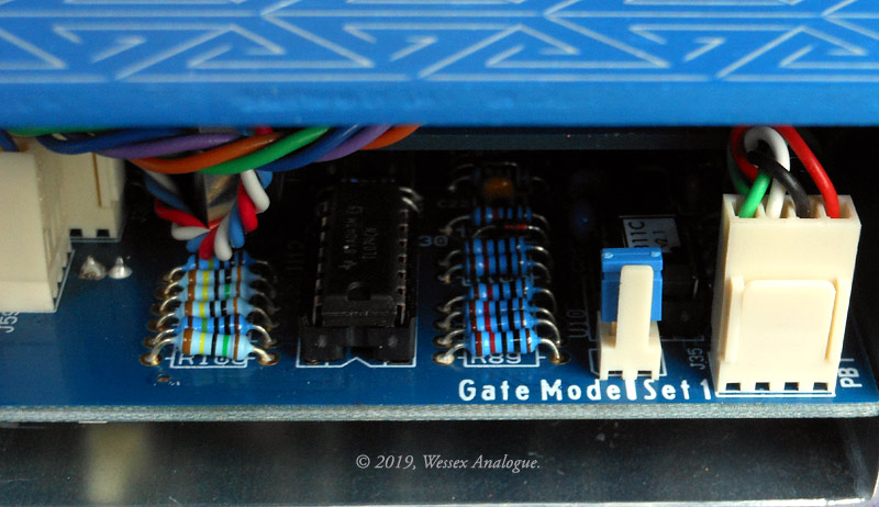
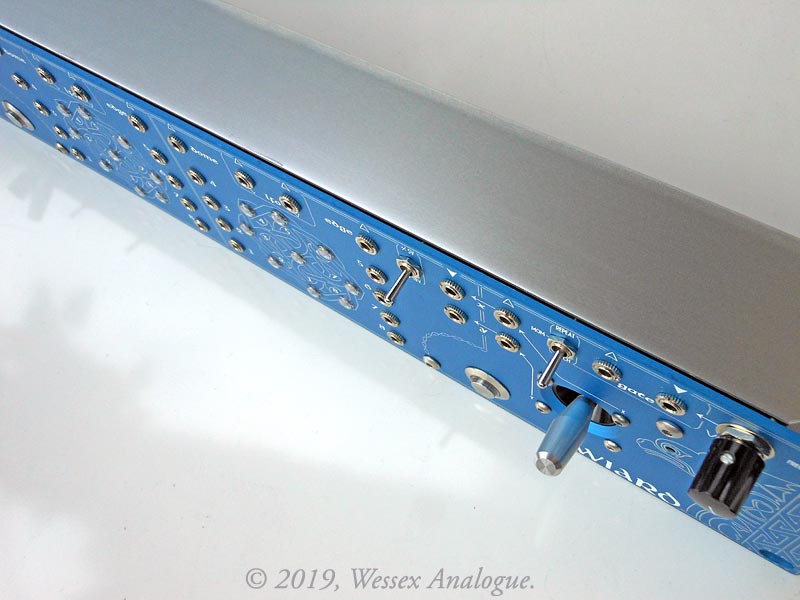
Removing a jumper link on the main board will switch to a second gate mode set (independent jumper for each side). In the second mode set, the centre position remains the same (momentary). The top "Repeat" position now allows the LFO or gate input signal to pass through the gate circuit and then to the gate output, regardless of button position, and if the button is pressed, the gate is held on. The bottom position becomes a latching gated repeat mode (press to turn on gated repeat, press again to turn off). For maximum flexibility, each side of the controller can use a different mode set, providing easy front-panel access to all five possible gate modes. (DIY tip: An external switch could also be wired to the jumper pins for easy access. Pre-assembled wiring from compatible connectors to panel mounting toggle switches may be added as an option when ordering.)
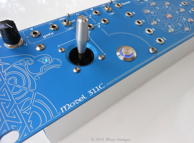
The panel is finished using a two-colour (blue and natural/silver) anodising process for the graphics and background, and overprinted in UV reactive ink for the legend markings and text.
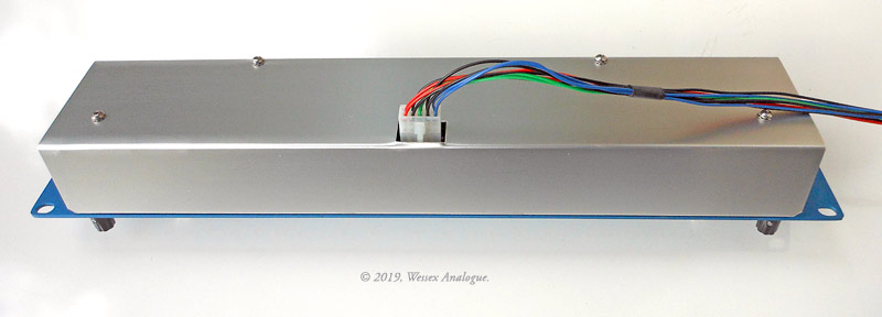
Designed for professional use, the rugged all through hole construction and premium components used throughout ensure a long life, and future serviceability.
Features:
• Two JAGs
• Two Joysticks
• Two Sine/Cosine LFOs
• Two Multi-mode Gates
• Bantam (TT) or 3.5mm jacks
Downloads:
Media: